Description
How to test the synchronism function (25) with software resources that facilitate and automate the procedure?
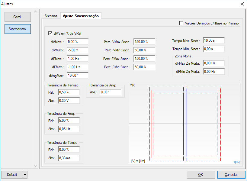
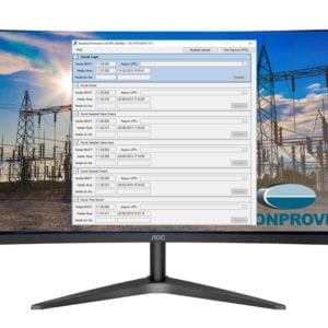
This software performs automatic tests on multi-function relays that have the function 25. It allows the user to adjust the voltage range by frequency and check if synchronism is possible.
The user can configure the tests specifying which generation channels are directed to the voltages, can also enable Pre-Simulation conditions 1 and 2 and a Post-Simulation condition. The configurations of system 1 and system 2 can be: single-phase – single-phase, single-phase – three-phase, three-phase – single-phase and three-phase – three-phase. Another important detail is the consideration of the breaker closing time, making the test as real as possible.
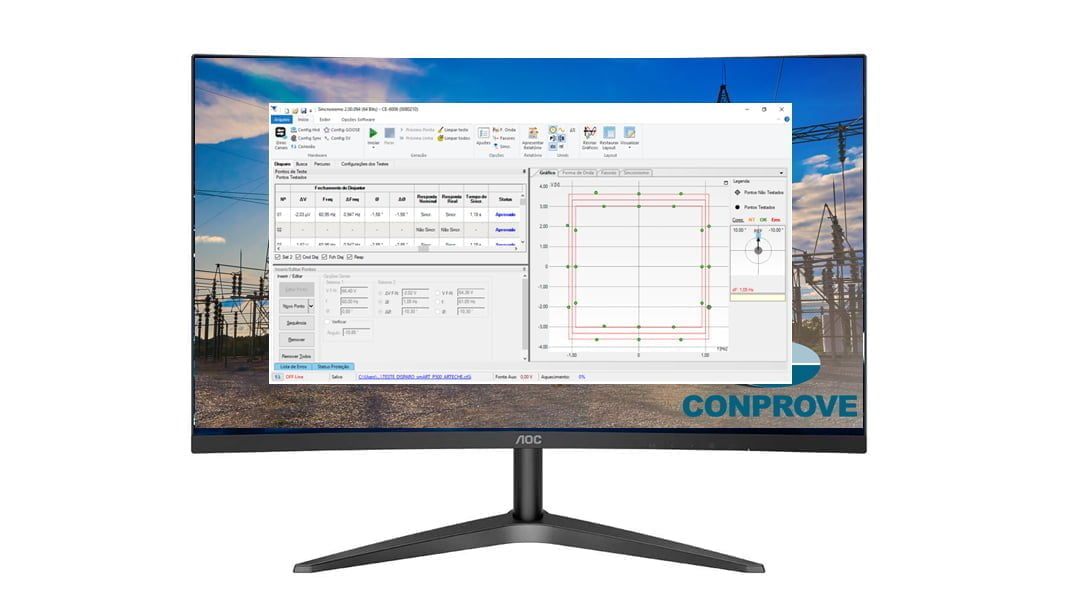
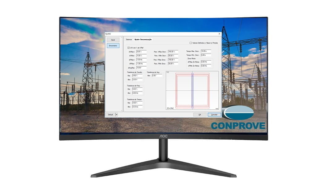
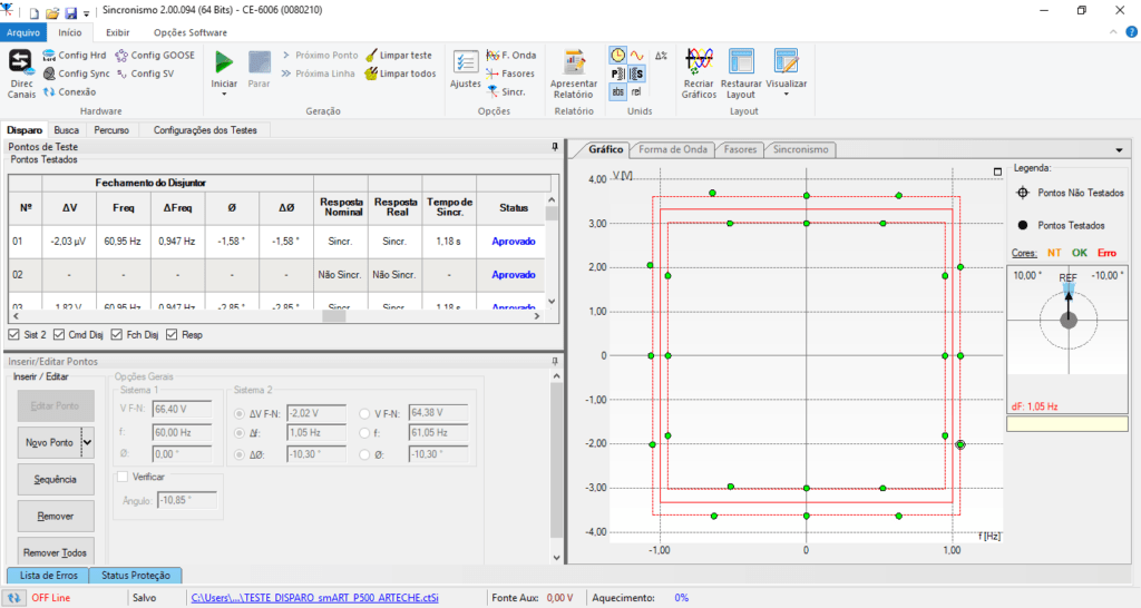
The tests performed are: Trigger Test, Search Test and Course Test. For all tests, it is possible to view the region where synchronism is allowed. To facilitate visualization, this region can be maximized and it also has a button for the purpose of transparency.
The software allows directing the voltage and frequency control interfaces to the Binary outputs for the voltage regulator and speed regulator respectively.
In the trip test, the user sets the module, angle and frequency conditions at a certain point in the synchronism plane. The idea is simply to check whether or not the synchronism will occur.
The purpose of the search test is to find the edge of the synchronism region based on the frequency (sub and over) and voltage (sub and over) actuations. For this test the user can insert a line or a sequence of lines. The data input are voltage, frequency and angle values. The software calculates for each line, based on the voltage and frequency signals, the increase or decrease of the modules of these quantities, in order to find the threshold between the region of synchronism and non-synchronism. Binary outputs must be set to “higher voltage” (V>); “Minor tension” (V <); “Higher frequency” (f>) and “lower frequency” (f <). At the end of the search, it is possible to define an angle interval for the software to check the synchronism.
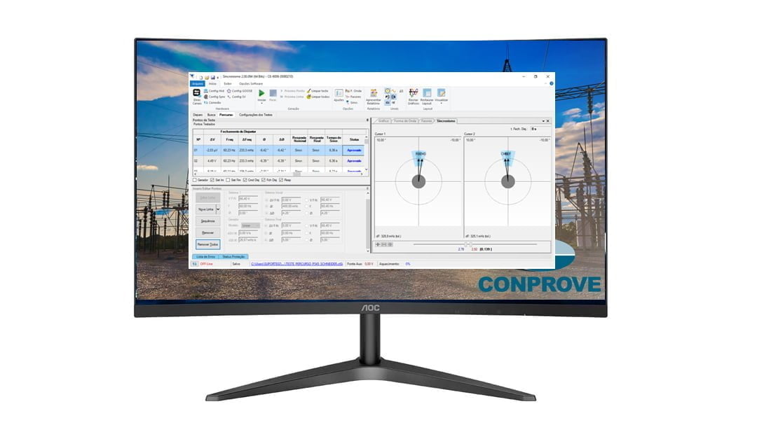
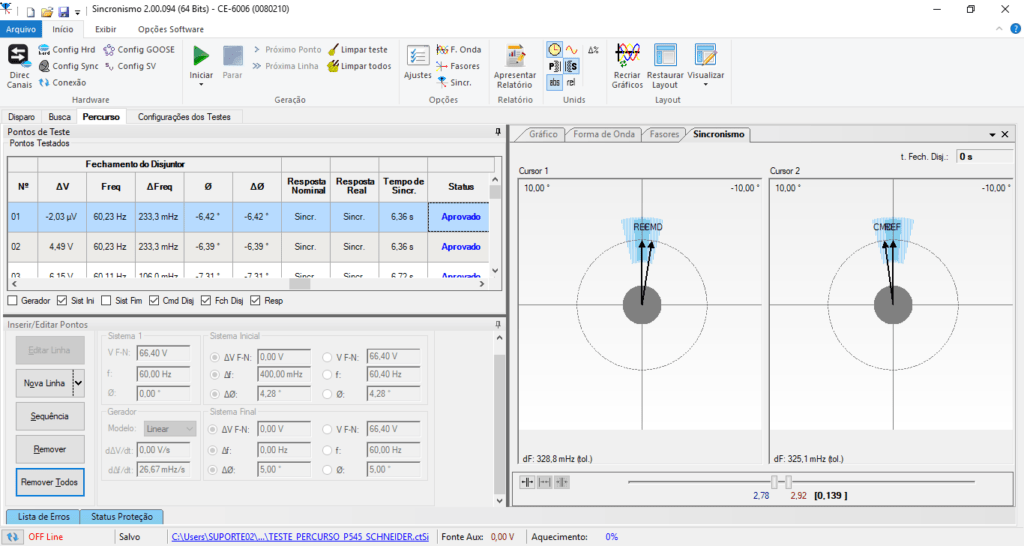
The route test aims to allow the user to test whether a system reaches synchronism even if there is a variation in voltage over time and / or variation in frequency over time, as well as the angle. Voltage, frequency are defined for system 1. For system 2, voltage, frequency and initial and final angle are defined. Finally, the values of the variation of voltage and frequency over time are adjusted.
To assist in the analysis of the tested points, the user has available waveform graphs, phasors and a virtual synchronoscope.






Reviews
There are no reviews yet.