Merging Units Testing
What is a Merging Unit?
The Merging Unit (MU) is an essential device that interfaces between instrument transformers at the process level and IEDs at the bay level. Its main function is to digitize current and voltage signals from the secondary of CTs and VTs, process this data, and publish it to the network in a standardized Ethernet frame, in accordance with the IEC 61850-9-2LE (“Light Edition”) or IEC 61869-9 standards, using the Sampled Values (SV) format.

What is the difference between a Merging Unit (MU) and a Stand Alone Merging Unit (SAMU)?
The difference between a MU and a SAMU lies in the type of instrument transformer to which the equipment is connected.
Low Power Instrument Transformers (LPITs) are non-conventional instrument transformers (NCITs), with low power output, developed to meet the operational requirements of substations, including digital substations based on the IEC 61850 standard. According to IEC 61869, to be considered an LPIT, it must produce at its output, under nominal voltage and/or current conditions, a maximum power of only 1VA (making it smaller, lighter, and especially safer).
For current measurement, it is common to use inductive low-power current transformers, Rogowski coils, or optical measurement using the Faraday effect. For voltage measurement, resistive, capacitive, or resistive-capacitive dividers are typically used. The output from these low-power instrument transformers may be analog (low amplitude signals) or digital, using standardized or proprietary protocols. These devices typically have MUs connected directly to their secondary, with this connection being proprietary or standardized. It is important to note that the MU output is always standardized using Sampled Values.
On the other hand, when the goal is to extend the service life of conventional CTs and VTs in the substation yard, delaying their replacement by an LPIT, a SAMU (Stand Alone Merging Unit) is used.
Video
Activate the English subtitle
What to test in the MU?
When testing a Merging Unit, some aspects are crucial:
- Linearity: evaluates whether the MU responds linearly in amplitude and angle according to the variation of injected analog signals.
- Frequency Response: checks the amplitude and angle errors at the MU output when voltage and current signals contain harmonics. The MU’s response to each harmonic order must be analyzed individually.
- Amplitude and Angle Accuracy: examines the accuracy of the current and voltage values at the MU output at the fundamental frequency, based on a static signal at the input over an extended period (long-duration test).
- Error Monitoring: this monitoring aims to assess the network’s health, verifying that there are no lost SV messages, corrupted messages, or duplicate or delayed samples.
- Statistical Time Monitoring: this monitoring aims to verify timing statistics in SV transmission and processing in the MU, checking whether the frame-to-frame time is consistent with the configured sampling rate and whether the sample digitization time plus the network transmission time remains below the 5 ms limit defined in IEC 61850-5 Ed.2, item 11.2.4 and IEC 61689-9 Ed.1, item 6.902.2.
- Synchronization Monitoring: this monitoring aims to ensure the synchronization of samples remains constant, maintaining their quality. To do this, the synchronization flag in the SV frame is evaluated.

Video
Activate the English subtitle
How to test an MU?
Verifying all the testing conditions described above ensures the MU is operating correctly, publishing current and voltage information reliably. This allows the protection system to operate successfully during a fault or avoid incorrect trips.
To achieve this, it is necessary to use a test tool compatible with all listed requirements. This test set must:
- Inject analog current and voltage signals with precision and flexibility in amplitude, angle, and harmonics;
- Subscribe to the SV frames published by the MU via optical fiber or RJ45;
- Process the received data, providing:
- Oscillography of waveforms,
- Phasor diagrams,
- Automatic percentage error assessments,
- Complete network diagnostics (packet loss, duplicate packets, out-of-order or corrupted packets);
- Timing statistics between frames and digitization time.
Additionally, the equipment should offer multiple time synchronization options, such as local sync or via GNSS, operate as a PTP master or slave, and be capable of acting as the network Grandmaster. Finally, the test set must generate complete and editable reports with the test results.
The ideal setup for testing is in a closed loop, which means:
- Synchronize the MU operating as a PTP Grandmaster (or, if necessary, provide IRIG-B signal);
- The test set injects analog signals into the MU;
- Subscribe to the SV frames via optical fiber (most common) or RJ45 to perform all analysis.

Conprove Solutions
To meet all the presented requirements, CONPROVE offers high-tech, high-performance, and robust solutions, ensuring that tests with Merging Units, as well as throughout the context of digital substations, are performed in a safe, efficient, and optimized manner.
CONPROVE offers a complete range of solutions to meet the testing demands of Merging Units, with powerful tools capable of achieving the most demanding accuracy criteria required in the process bus by IEC 61850 and IEC 61869-9 standards. In addition, they offer automation features that optimize protection testing:
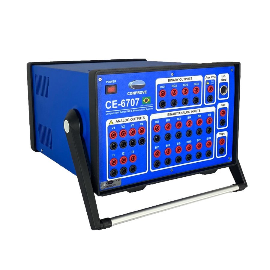
CE-6707: Universal Tester for Protection, Automation, Control, and Measurement; with Full Support for IEC-61850 / IEC-61869 standards;
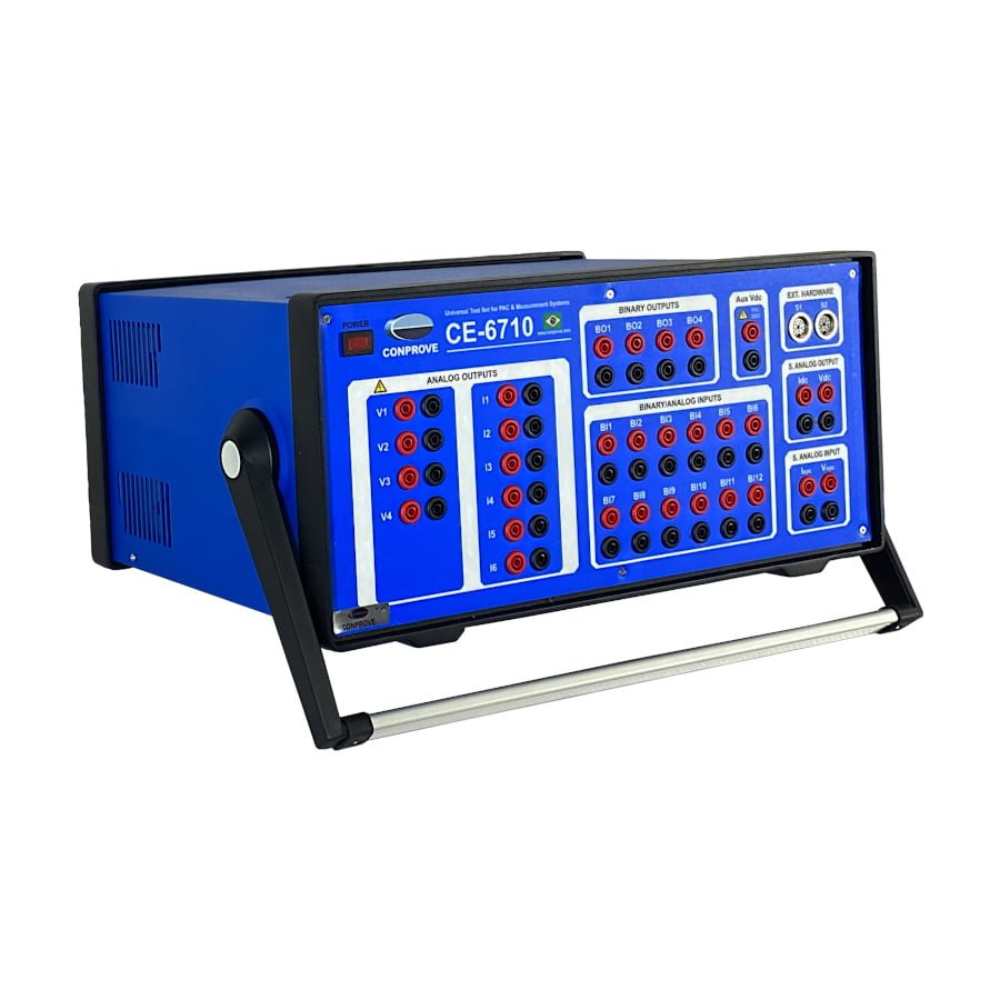
CE-6710: Universal Tester for Protection, Automation, Control, and Measurement; with Full Support for IEC-61850 / IEC-61869 standards;
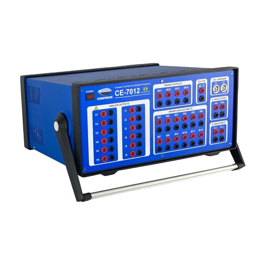
CE-7012: Compact Tester for Substation Systems (Primary and Secondary Levels) Microprocessed with Full Support for IEC-61850 / IEC-61869 standards;
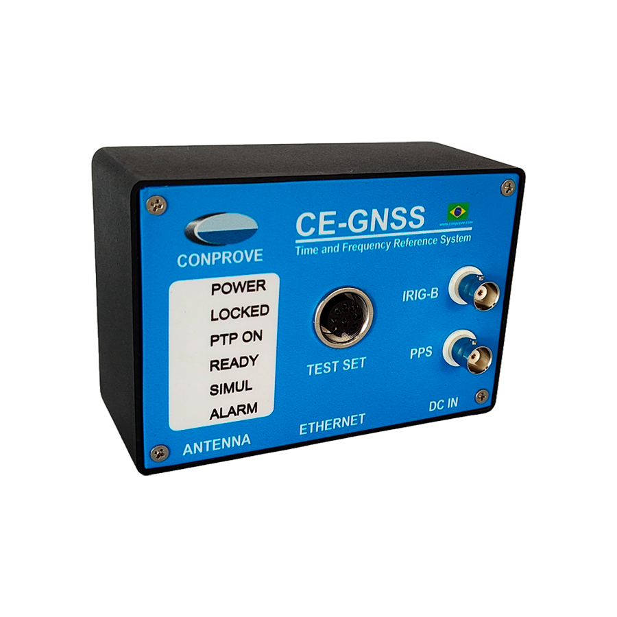
CE-GNSS: Global Navigation Satellite System | CE-GNSS – TIME & FREQUENCY REFERENCE SYSTEM;
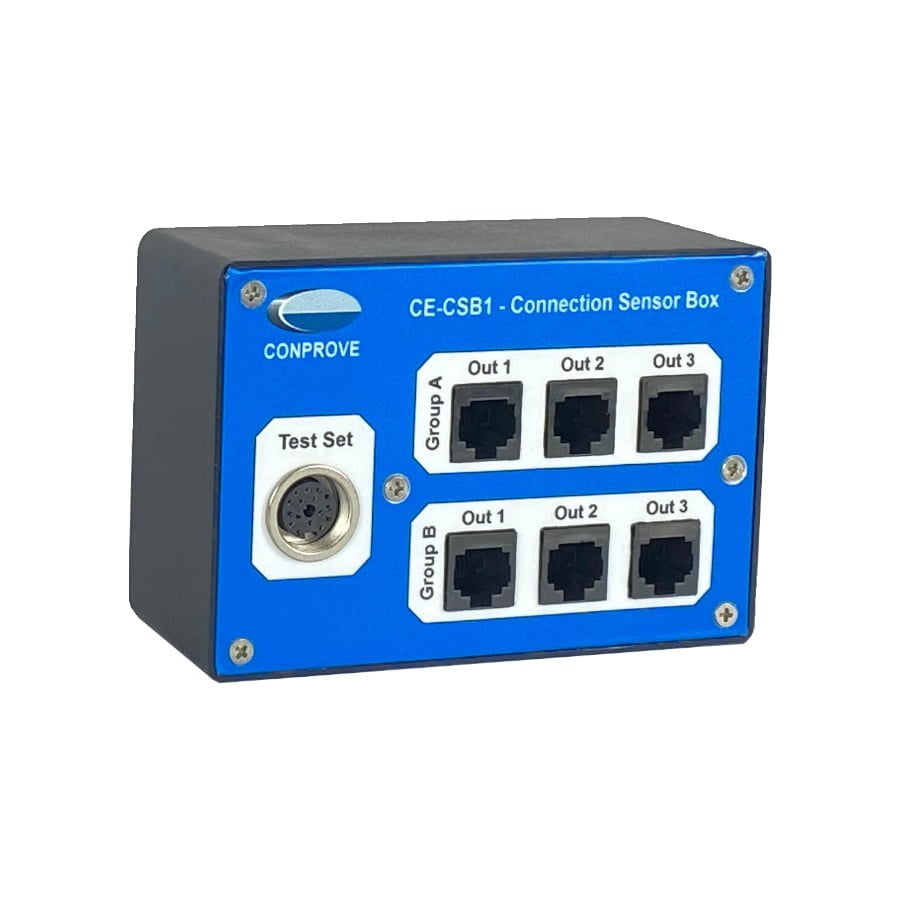
CE-CSB1 (Connection Sensor Box): Interface for Testing Devices with special input for Low Power Instrument Transformers (LPITs).


