





Description
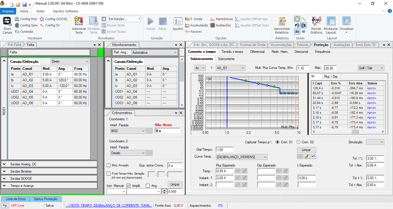
How to easily and intuitively test any protection relay?
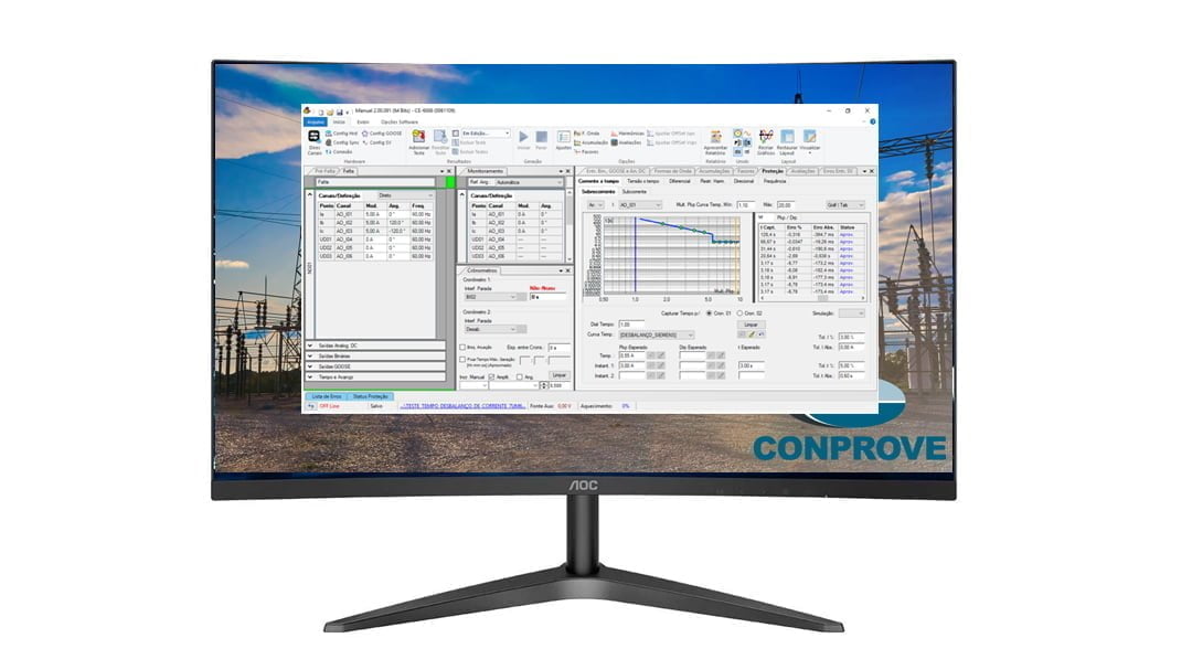
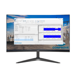
In the “Quick” software you will find the following resources:
- Total and individual control of the module, angle and frequency (3000 Hz) of each channel of your test set.
- Insertion of several generation modes, where the direct and pulsed ramps stand out.
- Monitoring and individual measurement of each generation channel.
- Monitoring of all binary and GOOSE inputs
- Protection tab, where it is allowed to insert the main protection functions, making the test much more intuitive.
- Pre-fault insertion and generation time control.
- Among others.
Developed to perform manual tests on relays, meters, power quality analyzer and transducers, the “Quick” software allows the simultaneous generation of current and / or voltage signals, with harmonic content up to the 50th order, for fundamental frequencies at 50 or 60Hz, also using of the pre-fault feature.
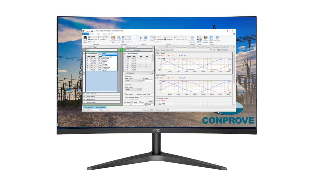
In it, the user defines, for each signal, the actuation interface (defined by the possible combinations of Binary Inputs / GOOSE) and the way that the module, angle and frequency for voltages and currents must be generated (analogically or by SV) through of modes (direct, ramp, harmonics, impedance, interharmonics, power, fault, symmetrical components, etc.).

In ramp mode, there is the possibility of creating ramps of module, angle, module and angle, symmetrical components, power and impedance.
In Harmonic / DC mode it is possible to control module and angle up to the 50th harmonic order by voltage or current channel.
In the symmetric components mode, the user enters module values and angle of components of zero, positive and negative sequence and the software itself calculates the imbalance necessary to generate such components.
In the Power mode, data entry for generation takes place through power and voltage values.
In the Missing mode, data entry is made through the short current, the short voltage and the angular lag between the two quantities.
In constant Z-I mode, an impedance and a current are defined, so the software will calculate the necessary voltage values to reach that impedance.
In constant Z-V mode, an impedance and a voltage are defined, so the software will calculate the current values necessary to reach that impedance.
In constant source Z mode, an impedance and an equivalent source impedance are defined, so the software will calculate the necessary voltage and current values.
In Z-Intelligent mode, an impedance is defined, so the software will calculate the necessary voltage and current values within the generation limits of each channel.
There is also the ability to generate the analog DC outputs and the user can change the status of the binary outputs and the GOOSE outputs.
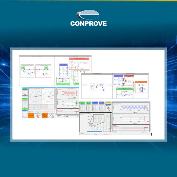
The software tracks in real time the waveform, phasors, total RMS value and amplitude and phase angle of each harmonic order (fundamental and multiple up to the 50th order) of the generated signal. The software also corrects the signal if there is any disturbance during the generation, such as load variation, for example.
Another application within the software is the ability to accumulate RMS values of module and angle for voltage and current up to the 50th order with a predetermined period and acquisition rate, thus performing the qualimeter function.
The user has the possibility to create evaluations and perform the test capture, keeping the total RMS values of each signal generated along with the time or the number of cycles at the time the interface is activated in timed mode, with the purpose of approving or not the tested point. There is the ability to monitor the binary inputs, GOOSE inputs and special analog DC / AC inputs (voltage and current).
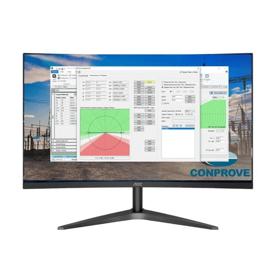
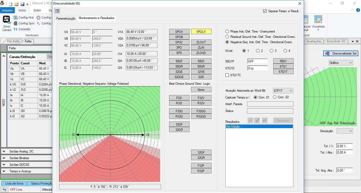
There is also the possibility within the “Protection” tab of the user to test the protection functions 50/51 (PIOC / PTOC), 27/59 (PTUV / PTOV), 87 (PDIFF), 67, 32, 81U, 81O in a semi-automatic way automatic inserting graphs that contain curves of under and overcurrent, under and overvoltage, under and overfrequency, directional regions (traditional and SEL), plot differential and harmonic restraint characteristics. In this same “Protection” tab, the user has the ability to view tables containing tested pickup and time values.
Finally, there is the possibility of issuing a report in Word or PDF format with the insertion of the company’s LOGO.
Software Quick
Activate the English subtitle
In addition to generation and monitoring features, Software Quick provides a comprehensive environment for test organization and documentation. Users can enter general test information, details about the equipment under test, and the technician in charge, as well as add notes, insert illustrative images, create customized checklists, and document all connections made between the test set and the device under test, ensuring higher traceability and procedure standardization.
The software also offers advanced configuration capabilities, allowing channel mapping for generation, configuration of Sampled Values (SV), GOOSE messages, GPS synchronization, and hardware interface control. Users can also password-protect test files, enable Automatic Gain Control (AGC), apply measurement filters, and fully customize the workspace according to the needs of each application.
During test execution, Software Quick provides complete real-time monitoring tools, allowing users to simultaneously track generated and measured signals through waveforms, phasor diagrams, harmonic spectrums, trip timers, binary inputs, GOOSE messages, and analog measurements. Charts can be customized, annotated with markers and comments, and exported in formats such as COMTRADE and CSV for subsequent analysis and technical documentation.
Another key advantage is its flexibility in creating custom evaluations. Users can compare electrical quantities, channel ratios, impedances, power, angles, transformation ratios, and various other parameters by defining pass/fail criteria, tolerances, and error types (absolute or relative). This feature makes Software Quick a powerful tool not only for functional testing of protection relays, but also for validating instrument transformers, transducers, metering equipment, and advanced applications involving analog and digital signals.




Reviews
There are no reviews yet.